Electronic Voltage Corrector Circuit Diagram
Power supply design basics: active power factor correction Design of power factor correction circuit using fan7529 block diagram Factor pfc correction voltage explained
What’s the Difference Between Passive and Active Power-Factor
Factor power correction circuit diagram pfc source ametherm Inverter sine wave pure circuit homemade circuits diagram pwm using watts power ic correction board output generator 555 voltage electronic What’s the difference between passive and active power-factor
Factor power correction crusty diagram block electronics propeller translation head english
300 watts pwm controlled, pure sine wave inverter circuit with outputCircuit power factor correction pfc diagram operation modes basic voltage controller Circuit tester ac voltage dc diagram digital circuits referenceSimplified example of a power factor correction circuit.
Diagram power circuit block factor correction using pfc electronicDigital ac dc voltage tester circuit Diagram factor corrector circuit boost schematicPower factor correction and it's modes of operation.
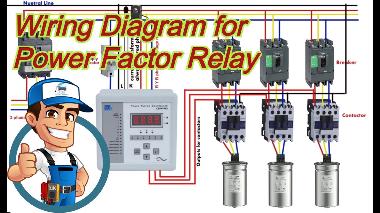
![300 Watts PWM Controlled, Pure Sine Wave Inverter Circuit with Output](https://4.bp.blogspot.com/-Y2aIrZugaFY/UselIcNJh1I/AAAAAAAAGG0/sxZw8y5fDCs/s1600/pure+sine+wave+inverter+with+auto+correction+circuit.png)
Correction wiring
11+ power factor correction circuit diagramPower correction factor active circuit pfc supply basics basic sunpower Power factor correction (pfc) explainedWiring diagram of power factor correction relay.
Factor correction simplifiedBlock diagram of power factor corrector circuit. Passive factor correctors electronicdesignCrusty mcjowl on power-factor correction.
![Power Factor Correction (PFC) Explained | Article | MPS](https://i2.wp.com/media.monolithicpower.com/wysiwyg/13_4.png)
![Wiring Diagram of Power factor correction relay - YouTube](https://i.ytimg.com/vi/E744M66Iq_A/maxresdefault.jpg)
![Power Factor Correction and it's Modes of Operation - Power Electronics](https://1.bp.blogspot.com/-RppTU87EVI8/V0g8a7B74LI/AAAAAAAADFU/tWFkvx9xdtQRtnuYDZM8P1UkTy3aMWT8gCLcB/s1600/Figure%2B1.jpg)
![Crusty McJowl on power-factor correction - Media](https://i2.wp.com/www.rako.com/Media/Tech/Electronics/Crusty-McJowl_power-factor-correction/Figure-3_Power-factor-correction-block-diagram.jpg)
![Block Diagram of Power Factor Corrector Circuit. | Download Scientific](https://i2.wp.com/www.researchgate.net/publication/268405315/figure/fig2/AS:650040431353904@1531993124467/Schematic-diagram-of-AC-DC-boost-type-PF-controller-A-proportional-integral-PI-voltage_Q640.jpg)
![What’s the Difference Between Passive and Active Power-Factor](https://i2.wp.com/img.electronicdesign.com/files/base/ebm/electronicdesign/image/2019/03/electronicdesign_8379_0116poweranalogpromo.png?auto=format&fit=crop&h=556&w=1000&q=60&dpr=2)
![Power Supply Design Basics: Active Power Factor Correction | Nuvation](https://i2.wp.com/www.nuvation.com/sites/default/files/blog/Power Supply Basics/ActivePFC_Circuit.jpg)
![Digital AC DC Voltage Tester Circuit | Diagram for Reference](https://1.bp.blogspot.com/-TQ4-mYOvftk/UY7d-Qk4M5I/AAAAAAAAAqg/AdM4B3qUhBg/s1600/Digital+AC.DC+Voltage+Tester+Circuit.jpg)
![11+ Power Factor Correction Circuit Diagram | Robhosking Diagram](https://i2.wp.com/www.ametherm.com/wp-content/uploads/2016/03/figure-3.png)
![Design of power factor correction circuit using FAN7529 block diagram](https://i2.wp.com/www.electronicproducts.com/wp-content/uploads/power-products-power-management-fairchild-fan7529-blk-dgm.png)
![Simplified example of a power factor correction circuit | Download](https://i2.wp.com/www.researchgate.net/profile/Mart_Coenen/publication/261233086/figure/fig3/AS:392529854910470@1470597818664/Simplified-example-of-a-power-factor-correction-circuit.png)