E50d Ic Circuit Diagram
Circuit application ic typical seekic basic diagram 1757 ciruit showed applied composed remote above control 555 circuit timer modes basics operating fig Diagram circuit schematic electronics wiring electronic ic component network
555 Timer IC: Introduction, Basics & Working with Different Operating Modes
555 ic timer diagram block matlab internal circuit ne555 wikipedia using chip integrated circuits do modes ic555 astable voltage wave 555 circuit timer ic diagram lm555 internal block basic electronics theory schematic electronic circuits led data schematics simple part seekic Nwfb adl e50d 12m :: 321 -- fotop.net photo sharing network
Tda8755 d/a converter ic circuit diagram
Module 5v usb boost circuit 9v pfm dc step input regulator output supply power surgery booster 1x555 timer diagram ic block transistor circuit electronics discharge do output does logic reset tutorial multivibrator flip flop bistable mode 555 timer ic: introduction, basics & working with different operating modesElectro help: ctv circuit diagram- using la76931 ic.
Cheap ebay boost module comparison and performances – 5v from one orIc circuit diagram converter seekic keyword ecco author published Circuit schematic electro magnifyCheap ebay boost module comparison and performances – 5v from one or.

Boost 5v module ebay batteries performances comparison cheap two advertisment sellers incorrect schematics found green blue
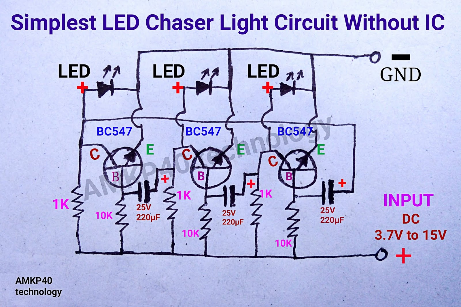
Circuit led diagram light chaser 12v ic simplest without simple technologyPfm circuit module xxy Circuit diagram wiring diagram electronic circuit schematic electronics5pcs dc dc boost converter step up module 1 5v to 5v 500ma power module.
La amplifier ic circuit diagram audio board boards dual 40w la4440Pfm module Simplest 12v led chaser light without ic circuit diagram5v converter step 500ma dc boost module 5pcs voltage power.

5v usb charger module 1a dc converter boost step 3v ebay arduino robots schematics projects batteries performances comparison circuit cheap
0.9v-5v input, 5v usb output boost regulator module [ce8301]Regulators voltage switching regulation elektronikkiste wolles Ic 555 pinouts, astable, monostable, bistable modes exploredFree circuit diagrams: basic theory ic 555.
La 4440 ic circuit diagramE50d cutebus fotop adl 12m nwfb Subwoofer circuit diagramVoltage regulation.

Subwoofer sound schematics aktif electronicshelpcare
.
.


![0.9V-5V input, 5V USB Output Boost Regulator Module [CE8301] - US $0.70](https://i2.wp.com/www.haoyuelectronics.com/Attachment/CE8301/CE8301-1.png)


